Objective: Retrofit wireless charging to a BMW E39 5-series.
Applicable Vehicles: 1996-2003 BMW E39 5-series: 520i, 523i, 525i, 528i, 530i, 535i, 540i, M5. Information from this article can also be applied to the 1994-2001 BMW E38 7-series: 730i, 740i, 740iL, 750iL, as well as other series.
Subject Vehicle: 02/2000 BMW E39 M5, DE93 USA.
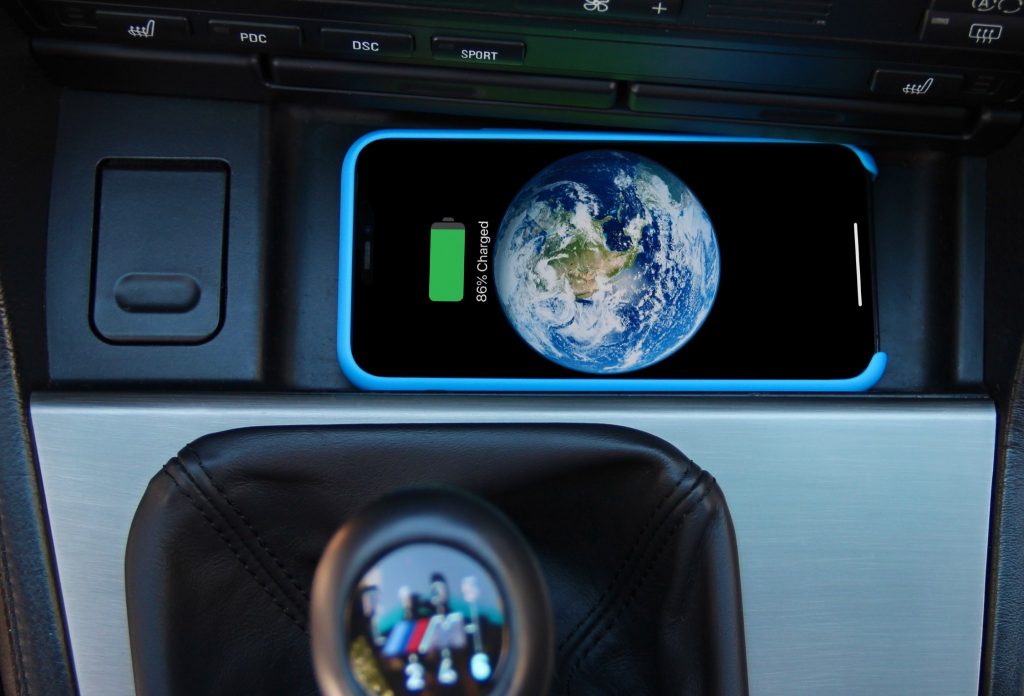
Preface: I will be installing my wireless charging coil/pad on the under-side of the plastic storage tray just in-front of the cup holders and HVAC climate control panel. My iPhone 11 Pro fits perfectly here, even with a silicone case fitted. iPhone Max versions will not fit here, as well as many other, larger Android devices. Update: my iPhone 12 Pro and 13 Pro have continued to fit and charge perfectly with this setup. You can install the wireless charging pad in any place that your phone will fit and not move around while driving. The magnetic field generated and used for charging from the charging pads is not large or strong, so it is important that it be installed in a way where it makes constant and consistent contact with your phone. We will use a voltage regulator to tap into a switched 12v line somewhere in the vehicle’s harness, there are many ways to do this. The voltage regulator outputs power via a micro-USB cable, which will plug directly into the wireless charging pad. It is important to note that wireless charging in your car will not supplement nightly charging, or a hard-wired cable if you need to rapidly re-charge your phone. It is intended to maintain or slowly your charge your phone while driving and using its navigation, cellular, or multi-media functions. I have found that even while using the phone’s function, it does still charge at a reasonable rate.
Parts Required:
| PART NUMBER | QUANTITY | DESCRIPTION | PRICE |
|---|---|---|---|
| 5823789011 | 1 | Wireless Charging Coil | $8.98 |
| B07H7X37T6 | 1 | Voltage Regulator | $9.39 |
| 51168159694 | 1 (if you want new) | Center Console Tray | $106.95 |
| QiCable | 1 (optional) | E38/E39 Plug & Play Eject-Box Wiring Kit | $80 |
Tools Required:
- Various Phillips screwdrivers
- Plastic pry tools
- Hot glue gun
- Drill or dremel
- Wire cutters
- Wire strippers
Difficulty: Easy. Center console removal, hot glue gun, wire splicing/tapping.
Time: 1-2 hours.
Procedure: Please watch the full video that is at the bottom of this post. It contains much more detail than this textual overview. This DIY requires 3 different jobs to be completed. I will outline each one, A-C.
A) Disassemble center console armrest, center console, and center console tray area.
- From the back seat, remove either your rear cup holders or rear storage cubby, located directly below the rear climate vents. For the cup holders, open both of them, and carefully pull outwards in the center. For the cubby, reach in, expand your fingers, and pull outwards. There are no fasteners holding either of these items in place.
- Slide the rear climate control vent down and remove the now exposed (2) black Phillips screws holding in the arm rest. The center console arm rest will now pull back and out.
- Remove the now exposed (2) more black Phillips screws under where the front of the arm rest was.
- Detach the shift boot or automatic transmission trim from the center console trim. The manual boot just pulls inwards and then up. It can be left in this position.
- Remove the now exposed (2) more black Phillips screws under where the front of the shift boot/trim was.
- Through the shift boot/transmission trim hole, press the hazard light switch and central locking button up and out of the console trim. Disconnect these switches and set them aside.
- Remove the now exposed (1) more brass Phillips screw from where the hazard light switch was.
- Twist the electrical connector ~45° for the cigarette lighter off of the center console trim. It is located on the left side of the console trim, and visible through the shift boot/transmission trim hole.
- Lift the center console out of the car, disconnecting the final electrical attachment that supplies the ashtray with power before completely removing the center console trim from the car.
- Open both front cup-holders half-way, revealing two silver Phillips screws. Remove these screws and pull the cup-holders out of the car.
- Reaching into the hole where the cup-holders were, push out on the multi-function switch panel that houses buttons such as the heated seat switches, DSC, PDC, sunshade, and Sport buttons. This panel will push out from the rear, where it can be disconnected and set aside. There are tabs on either side of the single electrical connector that must be pinched inwards while pulling on the connector.
- Reach into the multi-function switch hole and push the HVAC climate control panel out. It has several electrical connectors that must be carefully removed before it can be set aside.
- The frame that previously held the multi-function switch panel and HVAC panel is now held in with 4 more Phillips screws. Remove these screws and the frame/bracket.
- There are two more screws holding in the tray/lighter. They are back in the dashboard a few inches, so you will need a short Phillips screwdriver to remove them and then finally lift the tray out of the car.
B) Install the wireless charging coil/pad onto the tray.
- Decide how you want to rest your phone in this tray. For example, which orientation, closer to the left or right, etc. Test fit the pad while plugged into a powered micro-USB connector to see which way it will need to be installed for the best wireless electrical contact. Mark out the best orientation of the pad with a marker.
- The wireless charging pad will work through the entire plastic tray, but it will charge faster if we shave down some of this material. You can chose to skip this if you prefer, but reinstalling the tray back into the car with the charging pad on it may prove to be more difficult, as there is limited space in this area. I used a drill with a textured sanding bit to carefully shave down some of the plastic. Do not remove too much material.
- Give yourself a bit more slack on the attached circuit board and micro-USB connector by un-coiling it a few centimeters. This will be helpful later.
- Hot glue the pad to the back of the tray. The coil material will be mated to the bottom of the tray, with hot-glue holding them together. Allow the glue to dry for 15 minutes with some pressure holding the items together.
C) Wire the voltage regulator to a switched 12 volt source.
I am very happy to offer a plug-and-play cable that plugs directly into the 18-pin ‘eject box’ connector for power for the charging pad! This includes a voltage regulator, and is completely plug-and-play and the easiest way to install your wireless charger. Buy here. The required parts to build this harness are no longer available in small quantities, unfortunately. If you don’t see your eject box plug under the arm rest, it is probably tucked away under the console by the e-brake handle. You can cut a zip tie or two and carefully fish this connector out if you want. If your BMW is pre-wired for the phone (all USA E39s are), you will have this plug. On my 2000 M5, I found that pin #17 is ground and pin #8 is a switched 12 volt source. On my 2002 540i, I found that pin #2 is ground and pin #6 is a switched 12 volt source. I then ran my wiring and voltage regulator neatly through the console and up to the tray and wireless charging pad, where it plugs in with micro-USB. Use the following steps if you want to use a more traditional cut/splice method.
- Use a volt meter to locate a ground a switched 12 volt line near by. The closest power source will be the larger-gauge wires that power the cigarette lighter in the tray itself. These connections are not switched, however.
- Tap the wires with vampire taps and connect the voltage regulator.
- Plug the voltage regulator into the charging pad.
Re-assemble the various interior trim, switches, modules, etc. The wireless charging pad and associated small circuit board will fit when re-installed- if you removed enough material from the tray and are able to route the circuit board in a way that does not interfere with re-installation. If you are having trouble making these items fit, you can use a dremel to cut away at the plastic located directly under the tray. Do not remove more than would be absolutely required.