For the 2002 model year (from 9/1/2001 production), BMWs came standard with automatic headlights. Five components need to be installed or replaced to bring this functionality to earlier models. This article details the steps that must be completed to retrofit automatic headlights. Additionally, please view the video at the bottom of this post for more detail.
Objective: Retrofit automatic headlights to a BMW E39 5-series.
Applicable Vehicles: 1997-2001 BMW E39 5-series: 520i, 523i, 525i, 528i, 530i, 535i, 540i, M5. Information from this article can also be applied to the 1994-2001 BMW E38 7-series: 730i, 740i, 740iL, 750iL, the E53 BMW X5, and the 1999-2006 BMW E46 3-series: 323i, 325i, 328i, 330i, M3.
Subject Vehicle: 02/2000 BMW E39 M5, DE93 USA, with S521A Rain Sensor factory option.
Prerequisites: For this DIY, you will need to already have rain-sensing windshield wipers, BMW E39 option S521A – Rain Sensor. You can decode your VIN to check for this option here. While it is possible to retrofit both automatic wipers and headlights at the same time, that would require additional wiring since your vehicle did not come with the Rain Sensor connector, correct wiper stalk, and wiring to the GMIII central body electronics module.
Pre 3/1999 Cars: Vehicles manufactured before March, 1999 will either require additional hardware changes or coding. A different turn signal stalk was used from March, 1999 and the LCM IIIB will not recognize this earlier stalk. The newer turn signal stalk is available here. Additional wiring may be required, as well. To avoid changing this hardware, use NCS Expert to pull the FSW_PSW.TRACE file from the LCM executing the CODIERDATEN_LESEN job. Open the file in NCS Dummy, and find the “LENKSTOCKSCHALTER_ANALOG” parameter, and set it to ACTIV. Save the file as FSW_PSW.MAN and then use NCS Expert to write the file to the LCM using the SG_CODIEREN job.
DISCLOSURE: This post may contain affiliate links, meaning when you click the links and make a purchase, we receive a commission.
Parts Required:
61316909779 Automatic Headlight switch. $20.95 - $422.22
61316909780 Automatic headlight switch bezel. $438.47
61356923954 RLS (rail light sensor). $260.55
LCM IIIB or IV LCM (light control module). $50 - $350
GGS903KIT RLS (rain light sensor) prism kit. $32.95
GGS903PAD RLS (rain light sensor) pad. $12.95
61318363668 Turn signal stalk for pre-3/99 cars. $48.05 - $121.11
(The above prices are quoted from ECS Tuning. Other vendors may vary in pricing. Used parts will always be a cheaper alternative. Figures updated January, 2023.)
Tools Required:
1.T10 torx driver
Phillips screwdriver
Flat screwdriver
Plastic trim pry tools
Channel lock pliers
8mm socket and ratchet
19mm six-point socket and ratchet
Heat gun
Razor blade
Difficulty: Moderate. LCM coding/programming, windshield prism installation.
Time: 2-3 hours.
Procedure: Please watch the full video that is at the bottom of this post. It contains much more detail than this textual overview. This DIY requires 3 different jobs to be completed. I will outline each one, A-C.
A) Replace RS (rain sensor) and RS prism with RLS (rain light sensor) and RLS prism
Behind the rear view mirror, we will find the RS. The RS needs to be replaced with an RLS. They use the same plug, so no wiring modifications are required. The RS clips onto a glass prism that is installed with adhesive on the inside of the windshield glass. The RLS uses a different prism that must replace the existing prism. The prism kit comes with a new prism (now plastic) and a pad (adhesive pad) already applied to it. Buying additional pads will afford you more opportunities to install the prism correctly (without air bubbles between the adhesive and glass.)
Pry apart the plastic trim that covers the RS and base of the mirror with a pry tool.
Remove the rear view mirror by twisting it ~45 degrees where the stem meets the glass. Unplug the rear view mirror’s single 6-pin connector, and set the mirror aside. We can now see the RS.
There are plastic tabs on each side of the RS that hold it to the prism. Use a screwdriver or pick tool to pull the tabs out and away from the RS about 1/4″. The RS will now pull off of the prism, and can be unplugged and set aside.
The RS prism can be removed with a screwdriver, putty knife, pry tool, etc. Heat up and/or scrape off the RS prism glue.
Use a high quality glass cleaner to thoroughly clean the inside of the windshield and the ‘prism window’.
Crack the 3M primer tube and apply a thin layer to the area where the new prism/pad will install. Allow to dry for a few minutes.
Remove the protective paper over the pad on the new prism/pad kit. Use an ambient heat source (warm light bulb) to heat the glue on the pad.
‘Roll’ the new prism/pad onto the inside of the windshield. Avoid trapping any air bubbles between the prism/pad and windshield, these will interfere with the sensor operation. Be sure that when the RLS is installed to the prism, the sensor will align in the ‘window’ on the windshield, and be oriented the correct way (with the part number sticker visible from inside the vehicle when installed).
Install the new RLS onto the prism. Push the tabs up/in to secure the RLS to the prism. Plug in the new RLS.
Re-assemble the rear view mirror, and plastic trim covers.
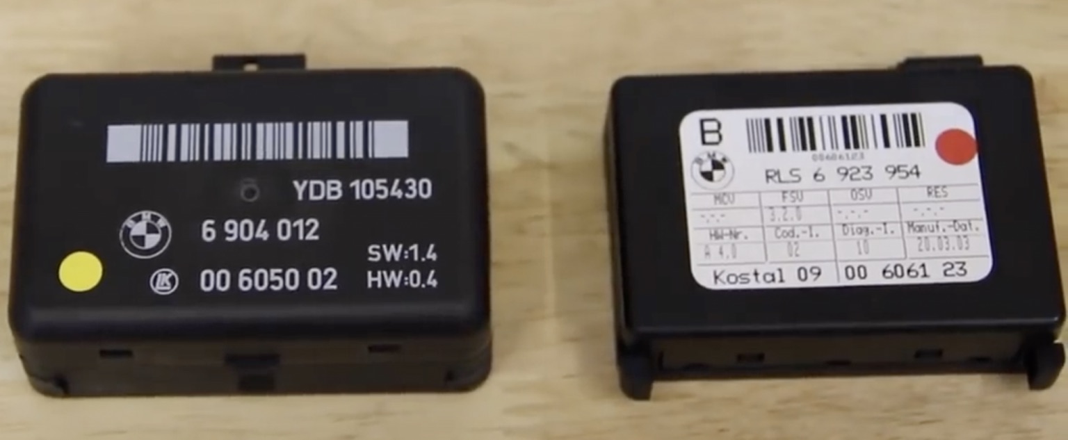
RS on the left, RLS on the right. The color dots are just my way of knowing which car they came from.
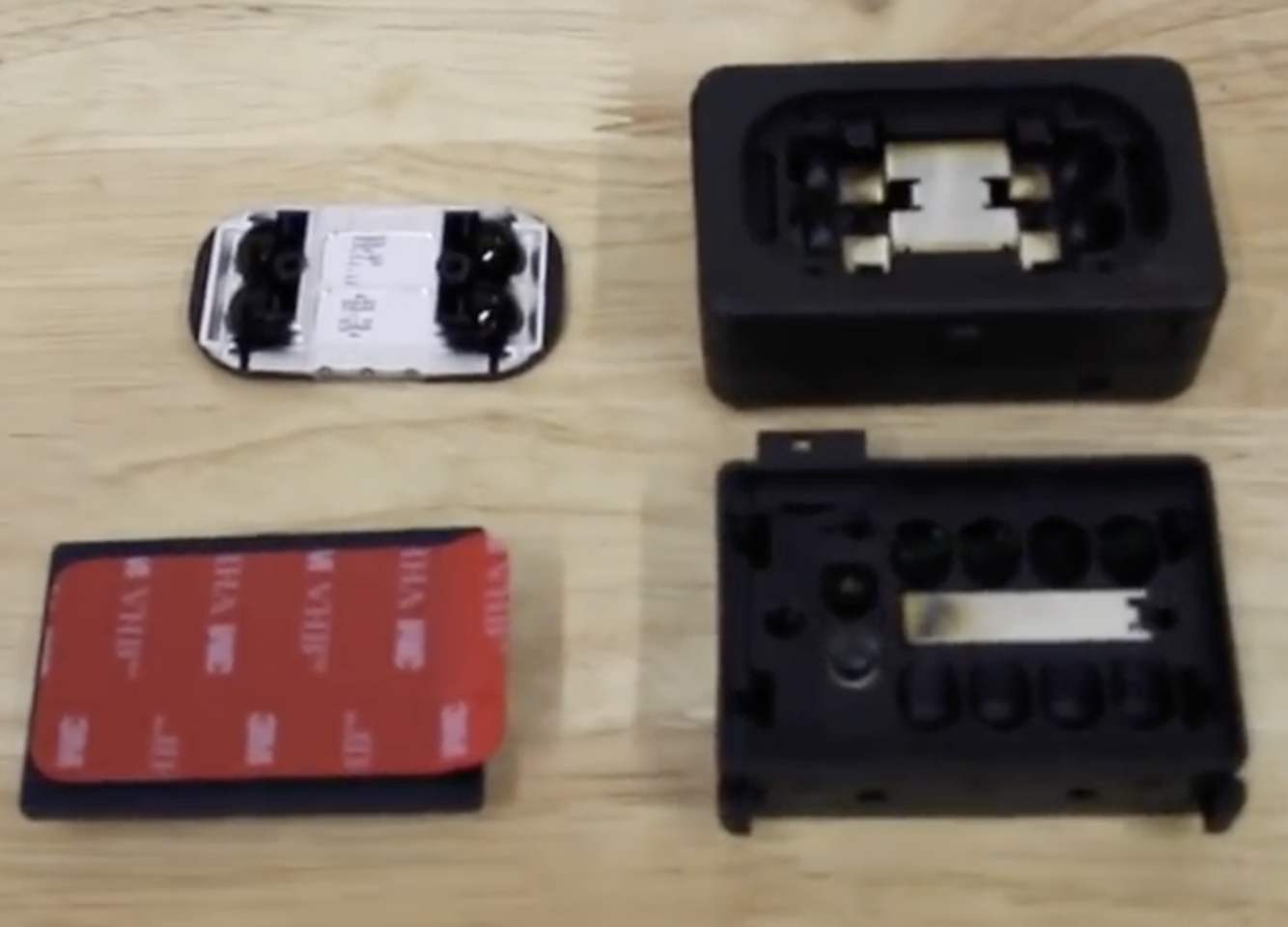
Top left: RS prism. Bottom left: RLS prism. Top right: RS. Bottom right: RLS.
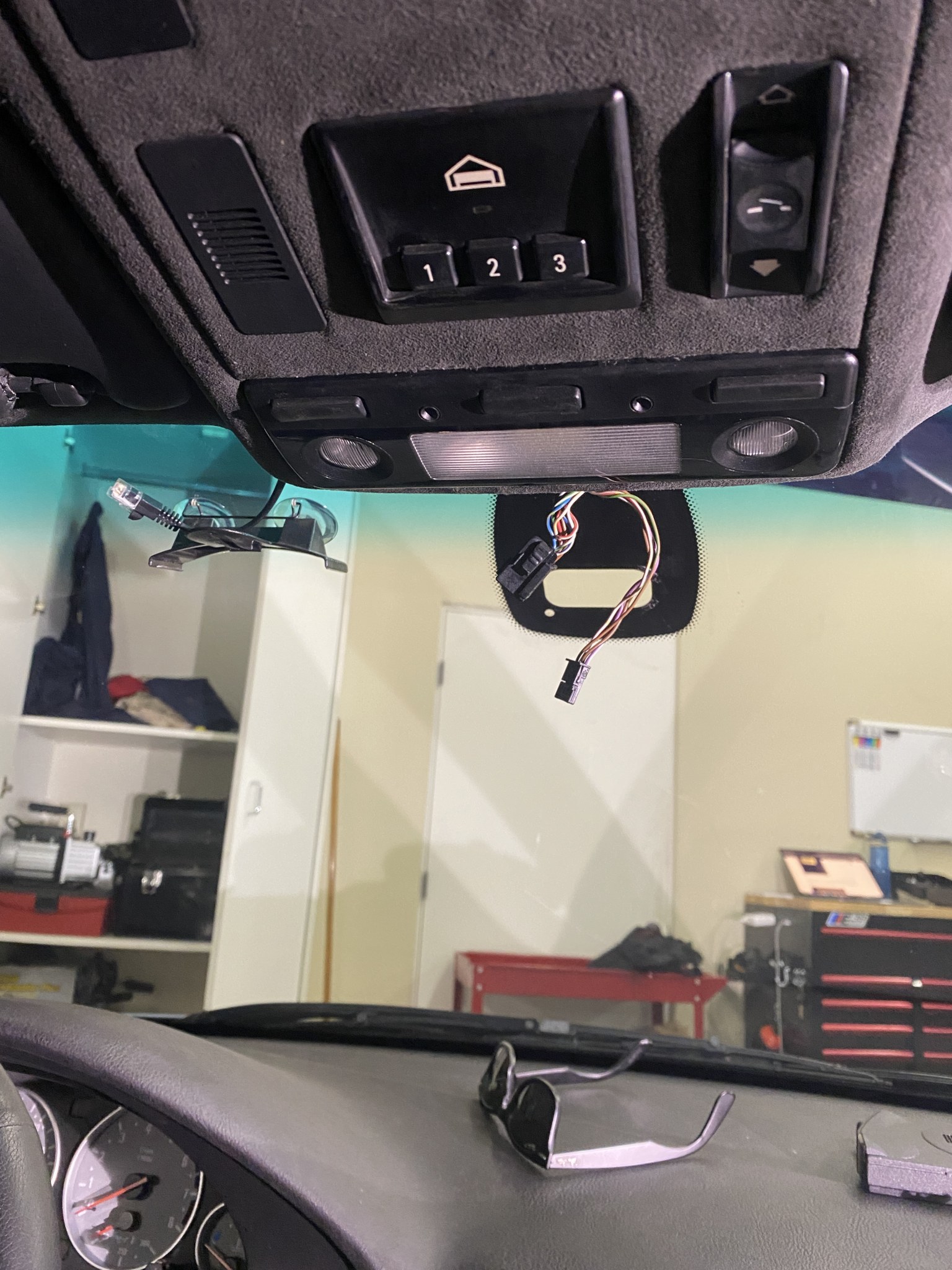
Old RS and RS prism removed. I refer to the hole in the black as the ‘window’ for the RS/RLS and prism.
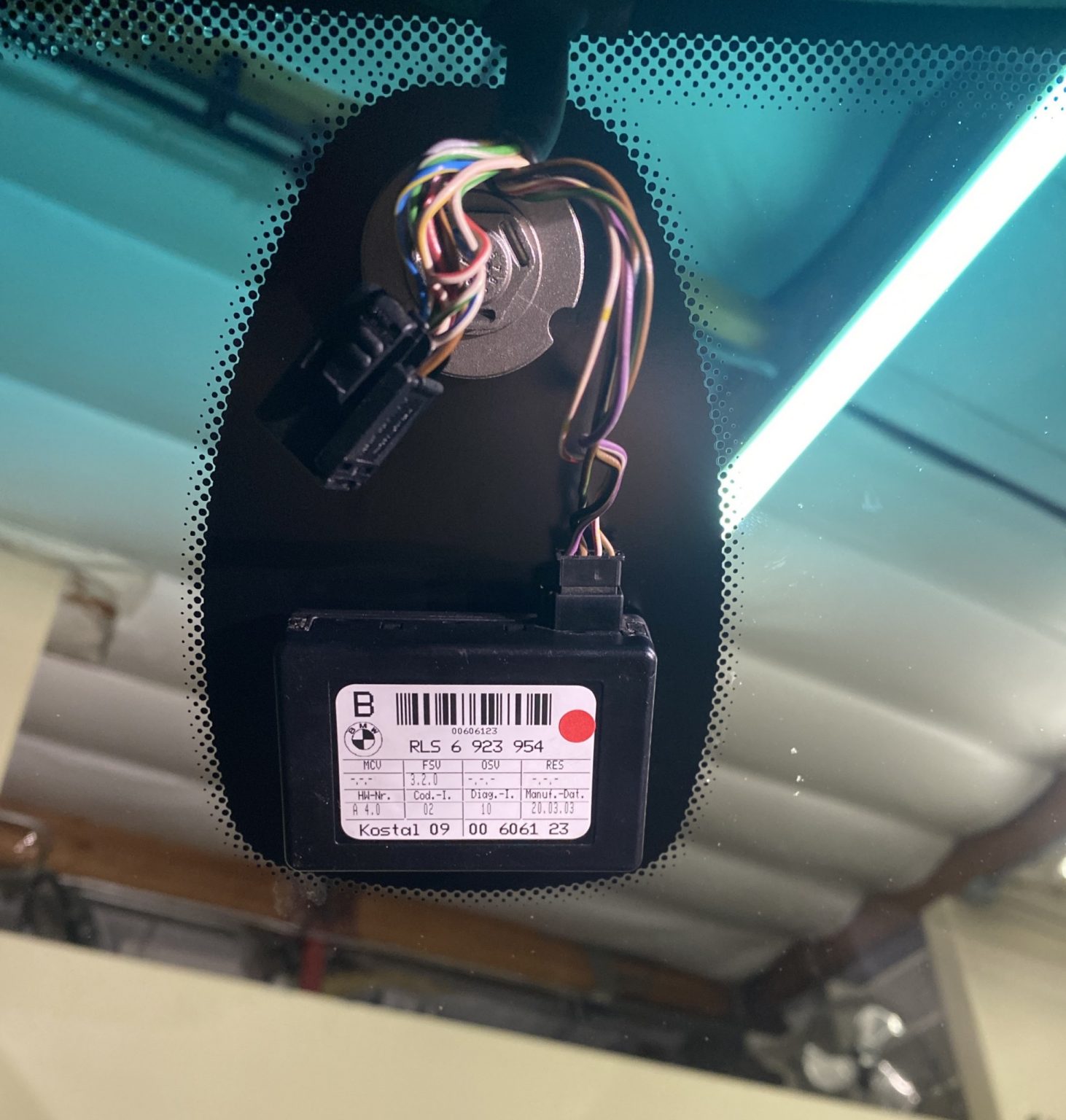
RLS installed!
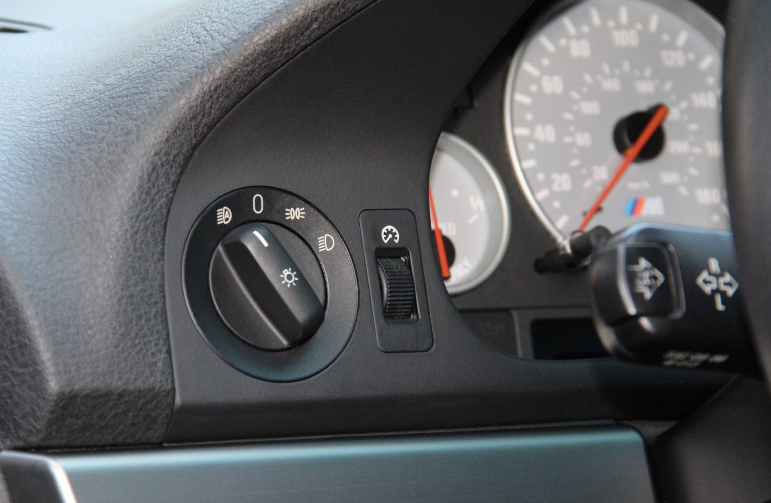
B) Replace the headlight switch, and headlight switch bezel
The headlight switch (electrical part) and the headlight switch bezel (surround with position labels) changed for auto lights. The automatic switches are purple instead of black for the standard switches. We must remove the instrument cluster trim surround, and replace these components.
Use a non-marring pry tool to remove your wood, aluminum, or other trim from the dashboard on either side of the steering wheel. These are the two 6-8″ pieces. They pull straight out of the dashboard. M5 only: disconnect tire pressure monitor switch (in trim) from vehicle wiring harness.
This will expose a total of 3 brass phillips head screws, remove them.
On the top of the instrument cluster bezel, there are 3 T10 torx screws that hold the bezel onto the dashboard. Remove them.
The instrument cluster bezel trim can now pull straight out, about 1.5 inches, and then be removed. There will be 3 electrical connectors attaching it to the car now. From left to right: headlight switch, dimmer potentiometer, fog light switch. Unplug all 3. Note that when you remove the headlight switch connector, the car seems to think that the light switch is now in position 1. To avoid killing your battery, either plug the car battery into a charger, disconnect the battery, or work quickly!
Use a thick towel/material to protect the headlight switch knob in the instrument cluster bezel. Now use channel locks to carefully but firmly pull the knob straight off of the switch.
Use a 19mm 6-point socket to remove the 19mm plastic nut that holds the headlight switch to the cluster bezel trim.
Remove the old headlight switch out the bottom and bezel from the top of the instrument cluster trim.
Carefully install the new headlight switch bezel, switch, and tighten (not too tightly) the plastic nut. There is no need for a wrench, simply twist the socket by hand. You can now press the knob back into place.
Reinstall and connect the instrument cluster bezel back into the car.
Reinstall the dashboard trim.
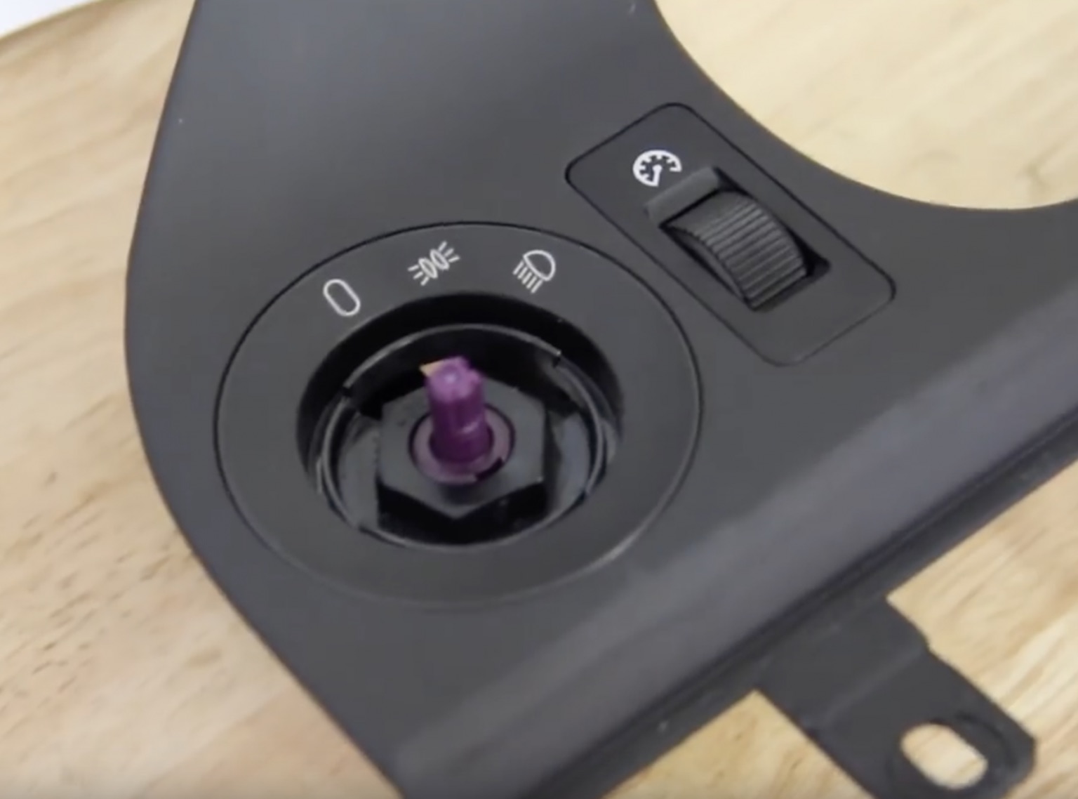
Headlight switch knob removed, 19mm black plastic nut removed. This nut holds the switch and switch bezel to the instrument cluster trim/bezel.
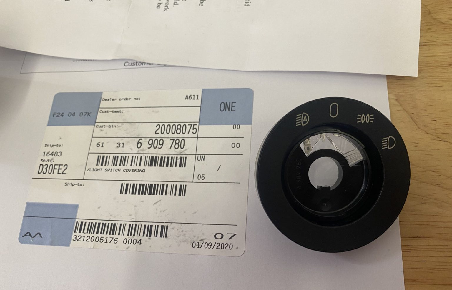
The last automatic headlight switch bezel in the United States, at the time (January, 2020).
C) Replace and program an LCM (light control module) IIIB or IV
An LCM IIIB or IV is required for automatic headlights. The LCM IIIB took over for the IIIA from 9/1/2001 production. All of the connectors and pin-outs are the same, so a swap is physically ‘plug and play’. However, the LCM is one of a few body modules that stores the vehicle’s mileage. Simply swapping your LCM II or IIIA for a IIIB or IV will enable the new automatic headlight function and work as designed, but you will surely see the tamper dot illuminated on your odometer. This means the car sees a mileage discrepancy and is alerting you of potential fraudulent activities. You should never just ignore this light, it could be a federal offense depending on where you reside. A new LCM IIIB or IV would be lovely, but BMW would charge a fortune for the part, and to program it. They will not program a used module that you provide them. You can buy used modules online, and program them yourself. You will need access to PASoft/BMW Scanner 1.4, or other software that is capable of pogromming the VIN, mileage, and options to an LCM. I demonstrate how to remove, install, and code/program the LCM in PASoft from 3:09 (m:ss) in the second video embedded below. Please see those clips for full instruction. Please do not contact me in regards to coding software setup. It should only be attempted by those who are computer-savvy enough to correctly configure the operating system, software, and device drivers. In this section we will remove your existing LCM, install a newer one, and configure it for your specific vehicle (VIN, mileage, options {such as daytime running lamps, check control settings}).
Buying the right LCM: high vs low
There are two main types of E39 LCMs: High and Low. High means high OBC (on board computer), or the instrument cluster that has the wide pixel display below the gauges that can say things like “FASTEN SEAT BELTS” or “CHECK ENGINE OIL LEV”. If you have this instrument cluster, you need to get an LCM IIIB or IV that was removed from a high car. If you have the low instrument cluster, you have the one that shows you which doors are ajar on a small display modeling a sedan, and you’ll need to source an LCM that was previous installed in a low OBC car.
Buying the right LCM: manual, auto, and no LWR
The LCM IIIB still uses manual LWR. LWR/LRA is a separate module, installed behind the glove box, that is responsible for leveling your xenon headlights (if equipped) up and down. If you do have xenon headlights (BMW option S522A Xenon Light) then you must get an LCM that says ‘with LWR’ (manual or auto) on the sticker. If you do not have xenon lights, you’ll want one that says ‘without LWR’ on the sticker. The LCM IV has the LWR function built in (‘with auto-LWR’ on sticker). I was unsuccessful in coding an LCM IV with auto-LWR to my M5, so I used an LCM IIIB. The choice is yours. Otherwise, the LCM IV has some additional settings that power-users may find useful, such as DRLs for halos, among other, more technical options.
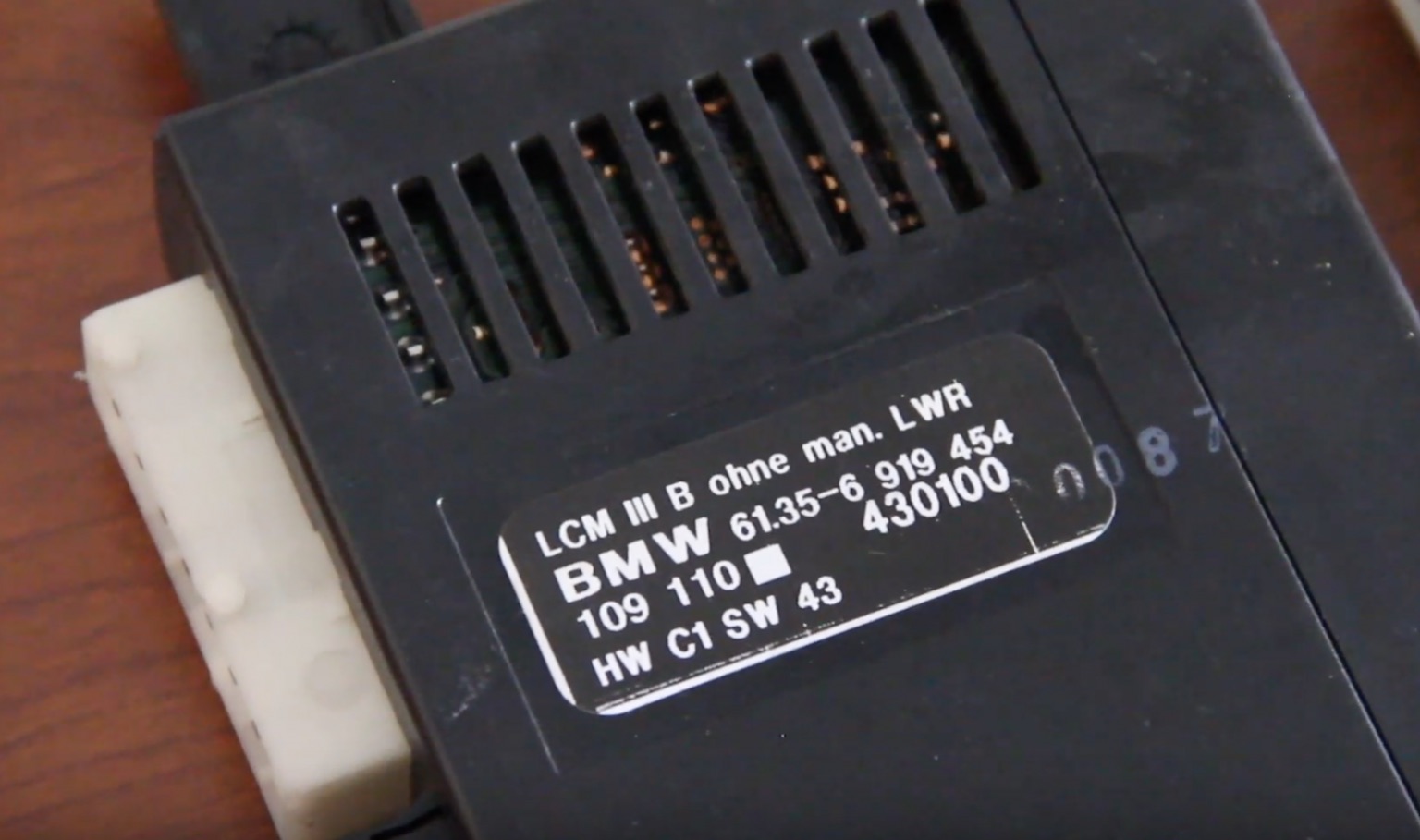
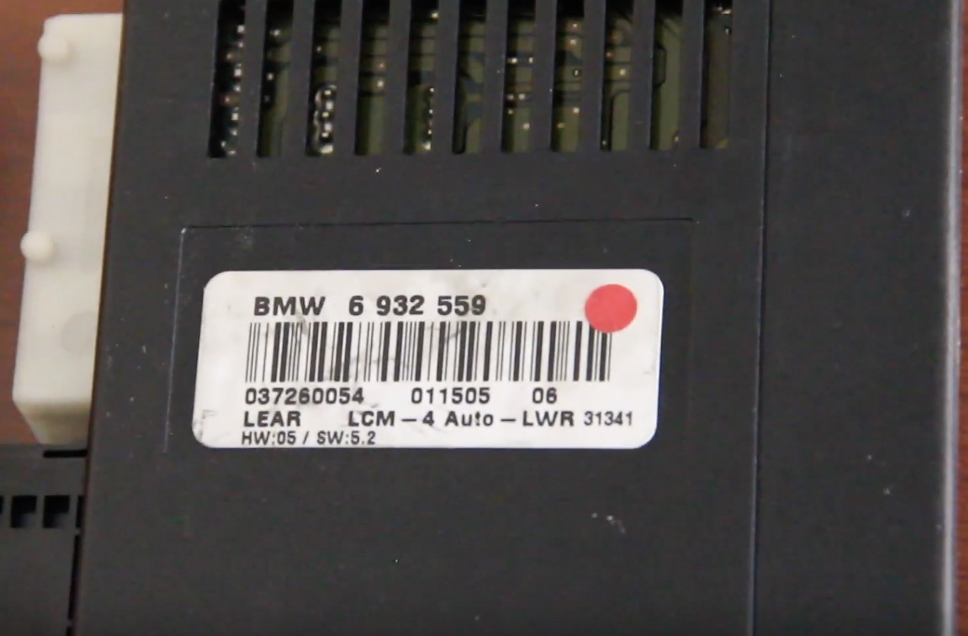
LCM IIIB sticker, high, with manual LWR.
LCM IV, high, with automatic LWR.
From the front passenger’s seat, reach under the the dashboard, and pull the ‘foot well ceiling’ towards you. This is a black piece of plastic trim. Set it aside.
From the front passenger’s sill/entry area, firmly pull up on the black, beige, or gray plastic grooved trim strip. It is held to the chassis with three plastic clips. Set this trim section aside.
Forwards of the last trim piece (step 2) is a curved piece of black, beige, or gray plastic where the door opening turns up towards the dashboard and glovebox. It is held in place with two plastic rivets. Simply pull/pry it away, towards the transmission tunnel, and set it aside.
Pull the carpeting back and and look up into this area, the LCM is the black vented module secured to the chassis.
Remove one 8mm bolt from the bottom of the LCM. This is the only fastener that secures the LCM to the chassis.
Disconnect each of the 3 connectors. The two larger ones (black, white) slide and push away simultaneously. The remaining connector (black) has a tab that must be depressed, which allows the lever to rotate, which pushes the connector away from the module.
Pull the LCM down and out of the car.
Plug the wires into the new LCM, and push it back into its home. The tab on the top of the LCM needs to slide into a faster that holds the LCM firmly against the chassis. Route the cables safely, and reinstall the 8mm screw with a socket and ratchet.
Reinstall the carpeting and three trim pieces removed earlier.
Insert the ignition key into the ignition and put it in position 2 (lights on, gauges active, engine off). The tamper dot will illuminate on the odometer- do not worry, we will fix this next.
Turn off un-needed accessories (navigation display, radio, headlights, climate blower motor fan, radar detector, etc). Plug in a battery charger to your car to preserve the battery charge during programming.
Launch PASoft or similar software, and connect your laptop/scanner to your car. If you have the round port under the hood, you must use it instead of the in-dash OBD-II port.
For PASoft: Launch the software, and open “LCM”
On the left, click on Change algorithm.
Find the numbers highlighted in blue and verify that the numbers match what the sticker on the LCM says. Verify that the MCU-IDNR (algorithm) matches what is programmed.
On the left, click on Reprogramming.
Click on Write FGSTNR (VIN).
Enter the last 7 digits of your VIN and click on OK.
On the left, click on Reprogramming.
Click on Write Odometer.
Type in either 0, or the current reading of your odometer (in KM). Typing 0 will allow the LCM to query the other body modules that store the VIN and copy/paste that value in when you first cycle the key.
If you wish to make coding changes, click on Coding data from the left, then Light coding, and configure these settings to your liking. Click Write. Note that flashing headlights, and dings from the instrument cluster are normal during coding.
Disconnect the software, turn off your key. Turn the key back on, the tamper dot will now disappear.
Test your system! You should be all set.
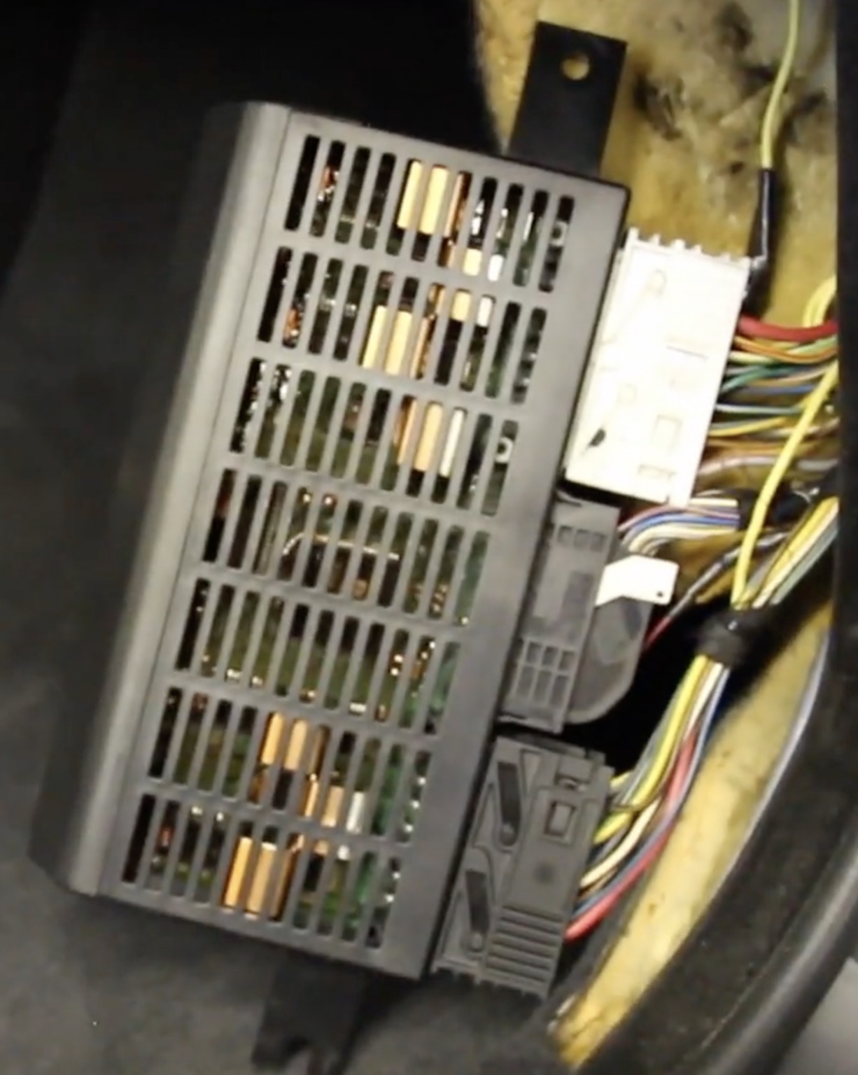
LCM wirings connectors. White (top) slides up. Black (center) lever slides and pulls straight out). Black (bottom) slides down.
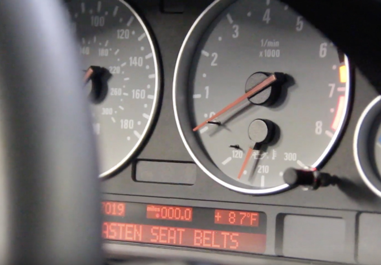
Tamper dot illuminated under ‘miles’ in the odometer. (Will be coded off).
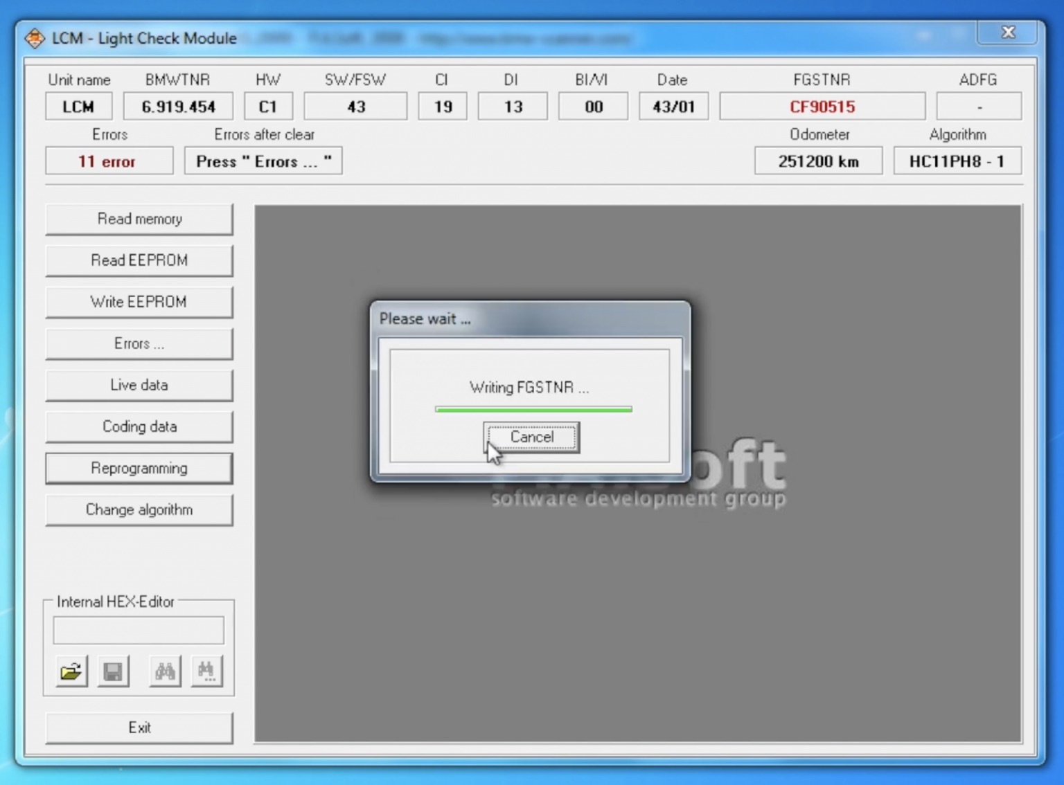
Writing the FGSTNR (VIN) to the new (used) LCM IIIB.
Troubleshooting: If you followed all of these instructions and used functioning parts, your setup should work as designed. If it is not working, go through each step again, and verify proper connections, coding, etc. Keep in mind that used modules can be a gamble, and could be faulty. It is common for used RLS modules to rattle when gently shaken. This is because resistors commonly fall off of the circuit board. These modules are generally faulty, and should be replaced with intact ones.
E39Source Full DIY – BMW E39 Auto Headlights Retrofit
LCM Removal/Installation, Programming, Coding